

お見積りをご依頼ください
24時間以内にご返信いたします。お急ぎの場合は、WhatsAppまたはWeChat(+8613188932181)までご連絡ください。.
*当社はお客様のプライバシーを尊重し、すべての情報を保護いたします。.
お客様の情報は、お問い合わせへの回答にのみ使用し、未承諾のメールや宣伝メッセージを送信することは一切ありません。.
 公開日
公開日
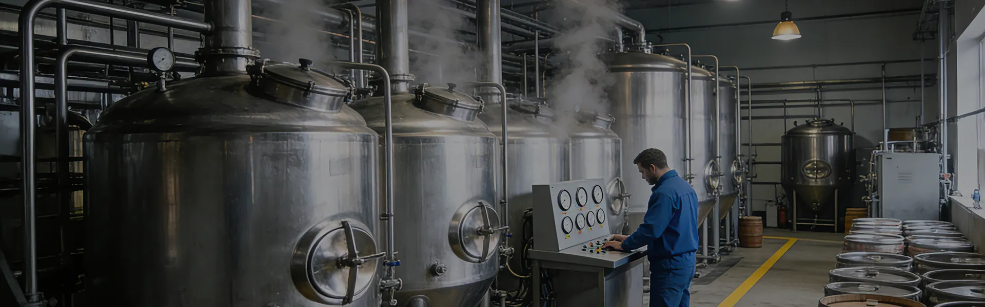
A useful brewery equipment diagram is more than a row of tanks. It shows how raw materials, wort, beer, cleaning fluids, utilities, people, and finished packages move through the building. That view helps a brewery team check vessel order, transfer points, pipe routes, drainage, access, and future expansion before equipment is fabricated.
This guide presents a practical process map for a commercial brewery. It is a planning framework, not a fabrication drawing. Final nozzle positions, pipe sizes, electrical loads, controls, and local code details must be confirmed against the selected equipment and site.
Start with five parallel layers. The first is the product path from grain to packaged beer. The second is the utility path for steam, electricity, water, glycol, compressed air, and carbon dioxide. The third is the cleaning path for CIP supply, return, drains, and chemical storage. The fourth is the people and material path. The fifth is the control path linking sensors, valves, pumps, and operator interfaces.
Label every vessel with its function and working volume. Mark transfer pumps, heat exchangers, filters, valves, sample points, hose stations, floor drains, and safe maintenance clearances. A diagram that only names tanks cannot expose a blocked forklift route or a missing utility connection.
For a three-vessel or four-vessel brewhouse, draw the vessels in the order operators use them, then draw the actual pipe connections. This makes it easier to spot a transfer that would require an unnecessary hose crossing or a pump that cannot reach the next vessel.
Hot-liquor and cold-liquor tanks are utility vessels that strongly affect the diagram. Show incoming treated water, heating or cooling duty, overflow protection, level measurement, and each destination. Separate potable-water lines from process-water lines where the site requires it. Include insulation, access, and drain points rather than treating the tanks as unlabeled boxes.
ZR Brew documents a 20HL Swedish project with a steam-heated three-vessel brewhouse and a 40HL hot-liquor tank. The project also includes six 40HL cylindroconical fermentation tanks and two 40HL pressure tanks. These verified capacities illustrate why the equipment diagram must continue beyond the brewhouse: the tank farm and its utilities determine much of the building layout.
After the wort cooler, draw the oxygenation or aeration point, wort transfer, fermentation vessels, glycol branches, pressure relief, and blow-off or collection route. Every fermenter needs a process connection, a cooling connection, a cleaning connection, and a safe drain path.
Next, show maturation or conditioning, filtration if used, bright beer tanks, and the route to packaging or serving. Keep product lines directional and identify where samples can be taken without contaminating the process. If a vessel can perform more than one duty, label the valve arrangement and control condition that makes the changeover safe.
For tank inventory and selection context, see the bright beer tank guide. For a larger planning discussion covering spacing and utility routing, review the 醸造所の設計・レイアウトガイド.
Draw the glycol chiller, reservoir, pumps, supply header, return header, branch valves, and each jacketed vessel. Identify the design supply and return temperatures only after the refrigeration engineer confirms them. Include pipe insulation, flow measurement, pressure relief, expansion volume, and access for pump and valve maintenance.
Do not size a chiller from brewhouse volume alone. Fermentation heat, crash cooling, cold rooms, pipe losses, and simultaneous tank schedules can overlap differently from one brewery to another. The brewery glycol chiller sizing guide explains how to turn that schedule into a documented load list.
A complete brewery equipment diagram includes a CIP supply and return loop. Show the CIP skid or tanks, caustic and acid circuits where applicable, spray devices, return pumps, temperature measurement, and chemical-safe storage. Each vessel should have a defined drain route that avoids crossing clean product lines.
Place floor drains at washdown points and low points, but verify slope, grate loading, odor control, and local wastewater requirements. Keep chemical handling away from ingredient and packaging traffic. A diagram that omits drains often creates the most expensive changes during installation.
Continue the beer path from bright beer tanks to the selected packaging system: keg filling, bottling, canning, or another approved format. Mark buffer tanks, filters, carbonation points, packaging utilities, rinse water, compressed air, CO2, labels, cartons, and finished-goods staging.
Separate incoming packaging materials from outbound finished product. Keep forklift lanes and personnel walkways visible. If packaging is scheduled in campaigns, show where hoses and temporary connections are stored so they do not become trip hazards.
The Brewers Association provides additional industry safety resources at BrewersAssociation.org. Use the applicable local engineering and safety requirements for the final design.
First approve the process flow. Next create a vessel schedule with working volumes, dimensions, weights, connections, and access requirements. Then develop a utility load list, a preliminary equipment layout, a piping and instrumentation diagram, and an electrical and controls package. Review each revision with production, maintenance, utilities, safety, and installation teams.
ZR Brew can coordinate equipment configuration, process-flow planning, facility-layout information, manufacturing, installation guidance, and commissioning support. Send the target capacity, beverage process, building constraints, utility data, and expansion plan through the ZR Brew contact page for a project-specific review.
No. A floor plan shows physical placement, while a process diagram shows how vessels, fluids, utilities, controls, and cleaning circuits connect. A coordinated project needs both.
Label the product path first, then add utilities, CIP, drains, controls, access, and safety points. This order keeps the diagram tied to production rather than becoming an unstructured equipment list.
The process layers are reusable, but vessel count, heating method, automation, packaging, utility loads, and building clearances must be designed for the selected project.
Future tanks change headers, pumps, cooling capacity, drainage, controls, access, and electrical service. Reserving routes and connection points early can avoid disruptive reconstruction.
Plan the process first, validate the utilities second, and place equipment only after both are understood.
24時間以内にご返信いたします。お急ぎの場合は、WhatsAppまたはWeChat(+8613188932181)までご連絡ください。.
*当社はお客様のプライバシーを尊重し、すべての情報を保護いたします。.
お客様の情報は、お問い合わせへの回答にのみ使用し、未承諾のメールや宣伝メッセージを送信することは一切ありません。.